I have this existing Soundbar in living room ! Not a great one but not so bad either:
Its a 50 W stereo speaker with built in subwoofer , a Aux in, Optical & RCA In and of course a BT 5.0 !
So my next question is , if I am happy to use this Soundbar for now , can I skip the amplifier and bookshelf speakers ? Not that I don’t want to spend but just thinking if it’s possible to use the existing Soundbar I have !
Also I only have a Projector and not a TV , that sends the laser beam on to my projector screen . I have a fire TV stick connecting to HDMI 1 of projector and another Pi 4 with OSMC (Kodi) installed and connected to HDMI 2 of projector ! Both fire stick and Kodi connect to Soundbar using BT !
Table below the projector screen has
a. Another PI with Hifiberry Digi plus card (192 kHz / 24 bit , optical out ) with Max2Play installed and connected to the Soundbar through an optical cable ! The Pi basically acts a HIFi multi Room Music Streamer and Bluetooth Audio Receiver !
b. My Sound Bar and
c. Alexa Echo Show
Can I just install the new PI with usb sound card & mic (Rhasspy Satellite) and place in on the table beside echo and Soundbar ? Is that bad acoustics and placement for mic ?
Yep, just get the plugable USB as wired or local it can still be used and unlike a hat (2mic respeaker) you can use multiple and also just as a usb soundcard.
Just use the Aux In.
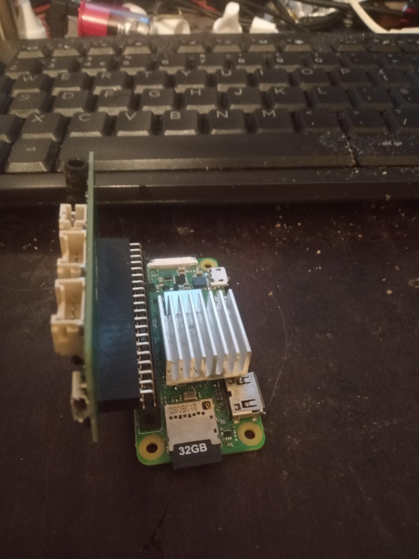
The Max9814 boards being wired just make it easier to mount and isolate than the 2mic due to being a hat it becomes all part of the pi.
Most people have the 2mic which is a linear board pointing at the ceiling because that is how it fits, but really the whole Pi should be vertical or use a 90’ connector.
Thats a 2mic hat 90’ it still becomes hard to isolate and Pi case don’t fit, so actually those Max9814 boards become a little easier as isolate those and the wires to the soundcard are flexible.
We are going to drop the pixel strip from the Mic, maybe still get one as they are cheap but need the logic level shifter.
Pi gpio is 3.3v whilst WS2812b is 5v and the above is supposedly bidirectional, so we can get it working and then worl out where ever it might go after, never tried so that bit for me is an experiment.
PS I have only ever seen these on ali-express but they make working with dupont jumpers when you need a common so much easier.
They are very cheap and handy for all sorts of gpio based connections and cuts down the solder jobs. https://www.aliexpress.com/item/1005003093298771.html
But basically as start its just to wire up x2 of those max9814 to a 3.5mm stereo jack to plug into the USB soundcard which is usually a screened pair Left/Right with screen being gnd, but also an extra 5v as the boards are preamps and powered.
Basically a DiY version of Array 2S Microphone - Andrea Communications which wil be better due the Max9814 and certainly not paying $45 for what is just a usb stereo ADC soundcard as the plugable one is every bit as good.
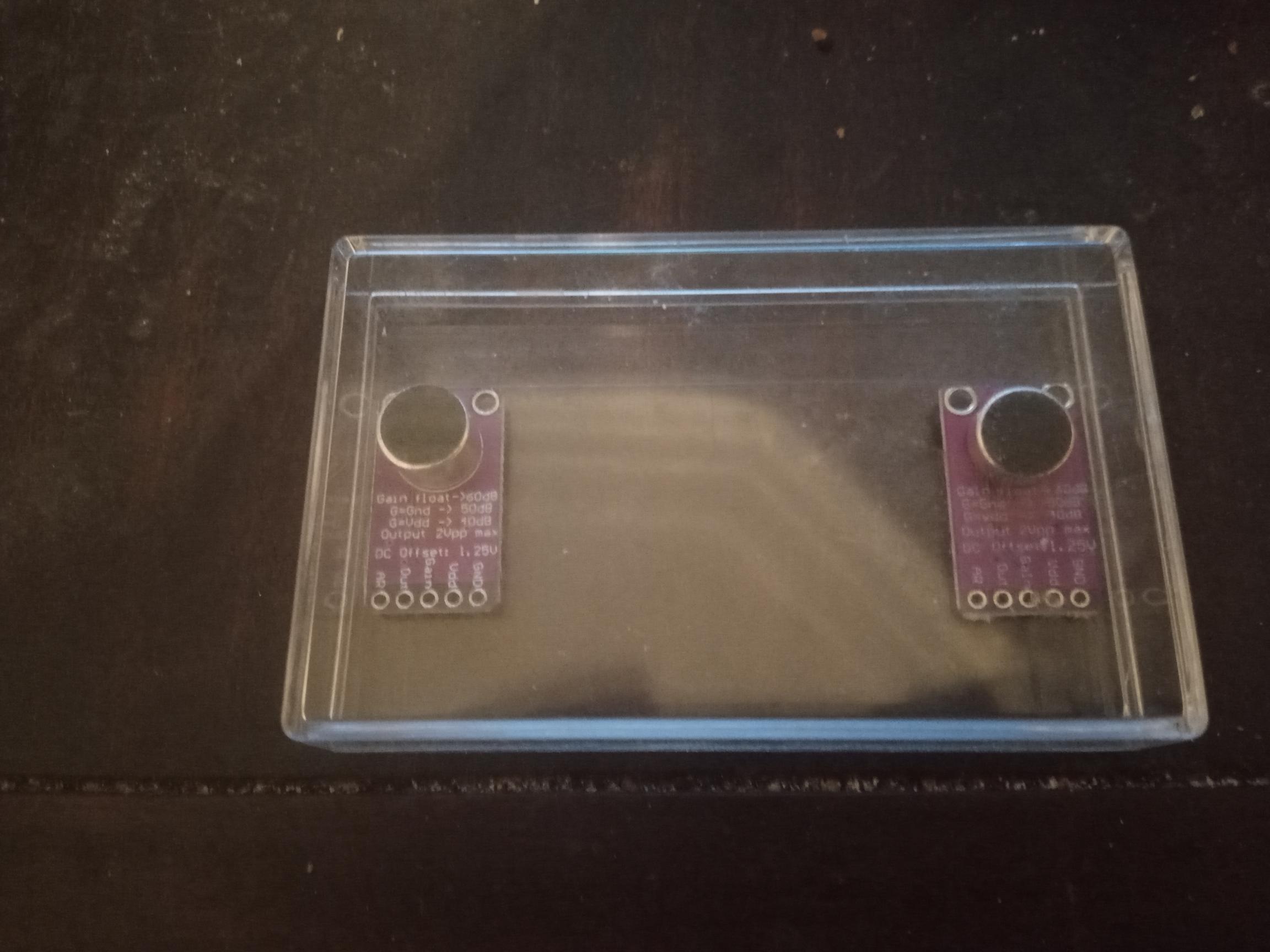
I haven’t drilled the holes and fitted the electrets in grommets but that is the test enclosure I am going to use and basically it will be just like the above andrea communication one but an active mic than passive that similary plugs into a stereo adc sound card aka Plugable.
Once again thank you for your guidance. You have been really incredible and your sound engineering expertise is immensely helping me understand the best practices for setting up Rhasspy ! Who have thought that an expert like you would be so willing to share his expertise and guide us ! That’s the real benefit of open source culture and I am absolutely loving it ! Thank you again !
I am trying to understand a few electronics basics with your help here. Apologies if they are sounding so basic but I am not experienced in hardware so much compared to my Software knowledge !
Why are we choosing electret mic instead of mems mic ? Is it because they have some kind of self noise cancellation from the back as compared to mems ?
How does the AGC on Max9814 help. Is it preamplifier ? Do we need it to increase the strength of microphone signal ?
How does Max9814 board with electret mic help towards overall noise cancellation alongside AEC or External noise cancellation ?
Why do we need to isolate Max9814 with electret mic ? Are we isolating it from noises and inferences coming from Pi ?
Does it mean can I use more than 2, say 4 Max9814 boards ? Does it help in far field voice detection or better direction or something else ?
If I use Max9814 boards , does it mean I don’t need a 90’ connector on Pi anymore as we are not using a HAT !
What’s the reason to prefer a usb sound card that has stereo mic input ? Does stereo mic input give us better voice capture features or something similar compared to mono ?
If I find a USB Sound card with stereo input 96 kHz sampling rate (something like a creative sound blaster) can I prefer to use it ?
I know I am sounding crazy on sampling rate numbers but if we use software AEC then anyway does it bring down the sample rate of music playing through the sound card Aux out to 16 kHz ? I saw that many hardware manufacturers such as those who make Remax 2 array USB with hardware dsp have only 16 kHZ. Does AEC limit the sampling rate to 16 kHz ?
I know that’s too many questions to ask ! I m only trying to learn some hardware basics from your experience ! If I set it up all correctly yes I will publish a DIY guide with due design credits to your knowledge !!!
Sound engineering expertise is purely referential as for some reason very little sound engineering is applied anywhere and my input is really rudimentary.
Electret is because of the Max9814 as its a sweet low noise preamp including selectable gain and AGC params.
There are mems avail but the preamp isn’t so sweet or has AGC.
Try them and see what you think as they are analogue and there is Speex AGC from the Alsa plugins.
I have selected the ones currently as the electret is onboard and its just less solder job and plug and play as my true preference is for these ones. Also being round they are extremely easy to mount in a grommet as with the mems avail those boards without even a mount hole are a pain.
As then you can choose the electret and swap from onboard omni-directional to one of the precursors to digital AEC of uni-directional noise cancelling electrets.
Or Farnel or RS unidirectional with the best sensitivity you can find.
They are front and rear ported where the rear port cancels as its in antiphase and that is my real preference but for some sourcing and soldering can be daunting so just went for ready made.
Its pointless to sample anything above 16Khz for the input to ASR as all use 16Khz or lower (near all use 16Khz) as 32Khz will double the load, 48Khz treble it, in fact it could be expotential and not linear and far more.
Also thinking this thread should be just trying some of your questions and getting some consensus so would be great if you had similar and that plugable is great value and good quality.
Could you please confirm if I am choosing the right hardware below to match our correct specifications / requirements ? I am a hardware noob at selecting matching specs, So trying to ensure I do not blast or burn anything !!! I will be ordering them today !
2x Max9814 with Electret and AGC
MiniBuck converter for pixel Led & Max9814 boards
Mini Buck converter for running Pi via GPIO 5v
Instead of this, can I use the one listed in point 2 above as it has a nice display ? However my concern is it has only 3A and a 5A is not available in pi hut !
Hard to find this brand elsewhere in UK and eBay just has so many duplicates ! Lucky I found one on Amazon UK !
2.1 Amplifier - I have decided to use an amplifier and bookshelf speakers for Rhasspy instead of use my existing Soundbar as it serves some other purpose !
I just need to look for
100watt 5/6amp 24v PSU
Bookshelf speakers
Ground Loop Noise Isolator
Audio Cables for Speakers
Arent Bookshelf speakers active and therefore connect to sound card / dac instead of Amp ?
Stereo 3.5mm jack lead with pigtail end to connect Max9814 to sound card
Just wondering how I can connect 2X Max9814 to USB sound card. I have seen your post from below but it talks about connecting to only one Max9814 !
Could you please let me know if any of these pi jumper cables are essentially useful for my Rhasspy DIY ?
Of course I can borrow a solder iron from a friend for very light soldering !
Yeah those look Ok and Pihut is a great shop and much of this are all Adafruit designs. If your happy with those prices then go for it.
I don’t usually like the adjustable bucks purely as its just more to think about and set, but I guess it does give you some tweaking room for the LED.
For a Pi GPIO power I would stick to 5v fixed as your jumpers should be short and at least no mistake can be made.
Again the boards I think are identical with the ‘I2C’ level shifter and dunno as have never tried but the freq should be able to cope with the 800khz Led control.
Plugable buy from amazon as have one on my desk that looks like one but definately isn’t purchased from ebay.
Use your echo or sound bar as a stock gap and you only need a Isolating transformer if using a buck from the Amp PSU to power both Pi and Amp.
The 3.5mm TRS Tip/Ring/Sleeve I forget L/R Tip/Ring or the other way Ring/Tip but doesn’t matter the Sleeve is the Gnd and that is the screen.
I have just the 3.5mm solder jack and some 4core + screen cable and about the only thing I can not find breakouts or terminals for.
Pi jumpers female/female always come in handy often I snip them in half and solder to cables.
Short/long female/female but tend to never need female/male male/male ones.
PS maybe also (you prob have already) an el cheapo single usb soundcard as you can also split the max9814 and on multiple cards but different pick up areas as a comparison. Again a couple $ and no imminent need as is an el cheapo lapel/car mic if you do an ebay search.
With your 3.5mm fly lead terminate with spliced female dupoints so you can swap between the 2.
If I remember rightly its tip& sleeve as the ring is something called ‘bias’
This presents the pinout and explains well as there was never really a standard, just most copying soundblaster cards.
Thank you for confirming! I had ordered all the above and a few of them will arrive within next week . I went with two buck converters one with the display and other with fixed 5V as you have suggested ! Still need to order some cables and speakers though.
I was just wondering how we are doing the speaker enclosure or if you suggest to use separate enclosure each for speakers, Pi & mics for better isolation !
Does any of the below work as terminal block for 3.5 mm Jack ?
Also do I need these to avoid soldering ? I mean can’t the headers on pi gpio use DuPont cables ? Also correct me if I need connecting anything else on the Pi pin headers apart from below !
Buck connector for led pixels
Buck connector for powering Pi from GPIO pins
level shift connector
Connecting Max9814 to Pi GPIO voltage pins
Just looking if I can avoid soldering all together in the whole solution ?
Also I guess I was able to find screw terminal blocks for 3.5 mm Jack as I mentioned in previous post and am guessing I can avoid that soldering too ?
Not that I hate soldering but yes I prefer to avoid it if possible !
Sounds a great Idea ! Yes so I was thinking of :
Pluggable USb sound card hooked to 2 Max9814
Another old creative Sound Card I already have. Hook it up to 2 more Max 9814 or may be a lapel/car mic ! Or lapel mics any better without AGC and amplification of Max9814 ?
I can still route Audio only through the Sound card I want and enable AEC for that . But how can we do echo cancellation if voice is picked by mics attached to sound card 1 and audio was playing through sound card 2 ?
Its the stereo TRS not TRRS even though the 2nd ring of a TRRS that on mobiles and such is used for the mic it could be possible to use that as the 5v for the active mic we are creating.
If you have managed to borrow a soldering iron I wouldn’t bother as having no soldering is great but they are big unweildly lumps, so up to you but prob hack away with what you have got so you can make a decision later.
There is a big question with AEC & Beamforming on a Pi if the results are worth it, or creating a cheap simple mic(s) of close proximity as even a Pi02 can run more KWS than it has threads and just add another USB or split a stereo soundcard to x2 mics of different catchment areas.
So just get the Mic stuff plug in to any powered speaker you have and without doubt if you still have the enthusasm next steps will be Pixel strips and Active speaker systems.
About the only thing I am certain about is that those Max9814 active mics being a preamp with AGC are a good start as often the gain circuit in soundcards is lacking.
So before you spend on all the extras I am wondering after your experience if you think AEC / Beamforming is worth the effort and effective.
Each one impacts on another and sometimes effects can be subtle but accumalitive and then the comparison to a single simple mic in close proximity.
Much of the problems are due not due to latency as in length of time but the variable latency the scheduling on a application SoC will provide.
So after trying various combinations ist likely try it again with a custom kernel such as
Asking again the question is it worth it.
You being software orientated there are some repo’s such as alsa-plugins, voice-en-aec & even Rtprempt Kernel and more that likely should have community forks so community hacks and fixes can be applied.
The answer could well be that actually we might be trying obselete methods and targetted blind source seperation is the way to go, but more than that the latency with USB is a problem and the variable latency of an applications SoC means really the answer lies on a true RtOS all embedded hardware.
Even simpler things as testing does potting the enclosure of the mic help with rear rejection and resonance through surrounding materials and once more is it worthwhile bothering with…
Thanks for the details. While I am awaiting the parts, I am still scratching my head on how to connect two mac9814s to a single UB sound card ! While connecting a single Max9814 to a usb sound card is pretty clear ! Could you please detail on how this can be done ?
Sorry for being so noob ! I am still not clear ! Can you provide a clear detail of connections between Pi , 2 Max9814’s and stereo 3.5 mm Jack cable with terminal blocks ? That would really help !
I will just tell you how I have done it as the terminal ones are too bulky for me.
I have a 4 core + screen cable but not using a core. I have Tip = Left, Ring = Right, Sleeve = Gnd (screen) soldered on a standard 3.5mm TRS jack and a dupont going to 5v.
Other side Left goes to 1 Max9814 with common Gnd & 5V, right goes to the other with common Gnd & 5V.
Well my question is mostly on Pi side! I am trying to think how to hook two max 9814s to Pi . As I said I m pretty noob in hardware so an actual explanation on how each connector from max9814 goes to Pi and usb card ! Thanks .
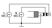
Note: A few, recently manufactured PCs have implemented true stereo microphone inputs. High performance speech recognition and advanced noise canceling applications – see the Andrea Superbeam Array stereo microphone – make good use of this new feature, providing more accurate and reliable signals in noisy environments.Stereo computer microphone schematic diagram
When the stereo mic input mode is selected, the bias voltage will be provided for both the tip and the ring. The wiring for a stereo microphone is simple – see the schematic diagram on the left – connect the shield of both microphones to the sleeve of the plug, the left mic to the tip and the right mic to the ring. For best performance, use unidirectional electret microphones.
One extra core needed for 5v from Pi5v to Max9814 5v not via jack plug. Haven’t soldered mine up yet but will post a pic.
Thank you. Sorry my mind has been somewhere throughout the day and just looked through this now and figured out as below :
Now that we have two of the below :
First or left Max9814
Second or right Max9814
The connections will be
Tip of 3.5 mm Jack = to Vdd pin on first Max9814
Ring of 3.5 mm Jack = to Vdd pin on second Max9814
Connect GND pins of first and second Max9814 and connect it to Sleeve (GND) of 3.5 mm Jack
Also connect Vdd pin on either of Max9814 to 5v on Pi (possibly Pin 2 or Pin 4)
Now that both Max9814s are in parallel , I need not worry as will both get the same voltage from Pi ! Also does it mean I cannot connect more than two Max9814s in parallel because we have tip and ring connecting to two Max9814s already !
And yes since we are about to use an amplifier PSU so we needed a Buck converter to step it down to 5V.
May be another rookie question - so are we leaving out Gain, Out and AR pins on both Max9814s ? This is the part I was getting more confused when I asked those questions to you in morning !
PSU is the only thing I haven’t bought , though I bought the Amplifier & other stuff as discussed ! So do you think a 100W, 24 V, 6A will cover our all needs of Pi, Led strip and Max9814s ? The 6 A is the thing I was getting concerned as Pi 4 requires 3.5 A and 1.8 A for Led strip ! That’s leaves another 0.7 A which is sufficient enough for both Max9814s ? I understand from data sheet that Max9814 draws very little current anyway …but please correct me if I am wrong ! (Afterall I am a rookie at electronics )
Yep that is what I am going to do, splice some female duponts as they are too fiddly to crimp.
I have those 2x 5pin headers though as a splitter for 5v & Gnd, also the AGC A/R (Attack release) pin I am going to leave as float, so no connection needed.
The gain as from memory the top gain 60db is a bit noisy, 50db is connect gnd so on that splitter it works perfect gnd-in splits to each max9814 gnd & gain pin, and 5v-in will just split to each 5v supply.
I haven’t added a pic of the cable as still scratching my head to where I have put the heatshrink and 3.5mm jackplugs that I have had for some time.
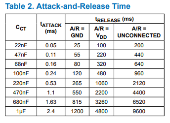
The CT capacitor Adafruit choose and all are copying was mid table whilst really for voice the slower attack and release would be better as the noise would take longer to occur and only during low input and silence.
With AGC Attack and Release almost logically seem to be the wrong way round but Attack is a fast response to clipping to attenuate and Release is a delay before the gain will start climbing to Max Gain.
Saying this as the Alsa-plugin for Speex-AGC has a single parameter which is effectively like the capacitor and it lacks a Max-Gain which is an easy fix as similar happens as it just ramps up into a noise floor.