Hi All, I have been looking over into this forum for a while to choose hardware for my Rhasspy satellite in Living Room . I am very grateful for the immense knowledge already shared across this forum. Especially huge respect to users like @rolyan_trauts who has shared great deal of knowledge for noobs like me !
I am looking for advice and feedback on below hardware i have chosen based on my satellite requirements.
I needed 192 kHz sampling rate on my Pi 4 - 2 GB as I also intend to use it as WiFi streaming endpoint using Squeezelite and Airplay.
I am basically looking to select one from the below two boards !
a. Can I use software AEC as detailed in Software EC with voice-engine / ec to make sure Rhasspy picks up my voice command when music is playing through this sound card at a moderate volume level ?
b. Can I still be able to pickup voice command from 2-3 m distance when there is external noise coming from TV with moderate volume level ! What sort of mic should I choose for this sound card that works even when there is external noise coming from my TV ? Can I use something like Boya microphone ?
c. Or Can I connect two MEMS I2S Mics to It and still ensure Rhasspy picks my voice command in external noise environment like when TV is running ? However it states we can only use dynamic microphones. Condenser microphones that require a phantom power supply are not supported. If MEMS is supported, Could someone please enlighten me how to connect them to this HiFiBerry board ??
Option 2
Raspiaudio Mic + V2
I am absolutely in love with this board as it supports 32 bit / 48 kHz output with 2X 5W speakers, one I2S microphone with high sensitivity !
a. Can I connect one more MEMS I2S Mic to It ( and have it working along with onboard mic ) and still ensure Rhasspy picks my voice command in external noise environment like when TV is running ?
b. Can I access the GPIO pins after stacking this hat as I want to connect an Neopixel Ring and use HermesLedControl !
For Speex AEC you either need a hardware loop back where the audio can be fed back so its recorded as a synced stream or a card that has audio in/out so that its synced by sharing the singular cards clock.
Also the hardware loopback needs to be a ADC type so you can just feed it an audio stream or you are just limited to what its playing, where many loopback a local I2S channel.
Depends how loud you shout As its not the distance of the noise its the ratio SNR (Sound to Noise Ratio) that KWS really start to struggle above 30% noise.
There is much you can do here but the Pi hat format of an open board in free air, is the absolute worst scenario for directional isolation and optimum performance.
But voice-en EC or at least the asound.conf is set at 16Khz as are many of the hardware solutions, problems that you need hardware loopbacks or audio in/out on a soundcard and to top it off a Pi of some simple DiY enclosure for speaker, with a whole host of other gotcha’s the simplest answer is no.
Then also why do you need 192 kHz sampling rate 16-bit, 44.1kHz is CD 48Khz is pro recording studio… ?
The amp on the Raspiaudio Mic + V2 2x 5watt is toy like for any consumer audio user?
I can say yeah to that, but been wondering of late even any WS2812b RGB string can be controlled with a level shifter as 3.3v is too low, so really any can.
Its actually really complex, no solution is really good and many ramp up into much cost where 3rd party noise is still a big problem.
Its why to simplify things because SNR is a ratio the simplest way is just to have a Mic with no AEC as close to you and as far away from noise.
I am an a self confessed audio snob, but I can put up with 16Khz but not 2x 5Watt speakers as apart from awful sound, the idea of stereo with no stereo seperation to give stereo offends my snob tendancies
I have had on my ToDo list for a long time as have all the parts gathering dust an audio snob on a budget solution, which really is far away from ‘Audio Snob’ but a very big step up from that 2x 5Watt, you will have to do some Ebay bargain hunting for a pair of 2nd user bookshelf speakers that should cost no more than a approx $25 and an amp of ebay/aliexpress, some as even as cheap as.
If you are interested in a long run wired beamforming mic, in fact I have various configs with a P4/3 wireless mic setup also but all using not the greatest but at least some speakers that can rival and in most cases outperform current Alexa & Google models.
I can giver you a part list and it will give me the impetus to do and document it here also and all the dirivative options, much is just about getting a mic close to you and and a really good pair of great sounding bookshelf (30-75 watt) book shelf or even 5.1.
I prefer Snapcast to Squeezlite as its just a wireless audio virtual cable that you can interface to any ‘Best of’ media player as Squeezelite is LMS with built in wireless virtual cable and I think there is better and for active singular wireless speakers the 3m latency compensation is no where near good enough, but fine from a single room amp.
So if your up for a project that could even be 2.1 and also be your TV audio system that for about $50 I could give you a part list to source and the thread could be the documentation I have been meaning to do for some while.
Hello rolyan , so thanks for writing to me. I am still trying to understand does it mean that I cannot use i2s mics because they are used up for loopback ? I quite understand the hardware loopback requirement but scratching myself to understand how does they affect me to use 2 mems mics with my sound card / dac ?
And yes i didnot mean the RaspiAudio as option 2 but for a small room / kitchen area so 2X 5W still would be adequate for such setup !
Yes I am admittedly becoming audiophile pointlessly insisting on 24 bit / 192 kHz ! But yes even 48 KHz should be very very fine ! However as you mentioned above if I implement voice-en EC, But it sets it to 16Khz then that means I am not even getting 48khz sampling rate then ?
Yup definitely I would be very very interested in such a setup ! Absolutely let’s please do it ! I am an experienced Linux user as I am into software engineering for more than 2 decades now ! But yes still a noob when it comes to hardware but I hope if you guide me I would be able to try out the interesting setup !!!
Ok start with a wired x2 channel microphone. I have examples but whereever is best and cheapest (aliexpress).
2x Max9814 as they have a silicon AGC so can be part of any prefilter and be the anti-clipping AGC.
They push fit into a grommet so one of the easiest to mount as just drill a hole, but also the grommet will give an element of isolation and a clean finnish.
Running 5vdc for any length is going to create a voltage drop and instead we are going to use the 24vDC from the amp PSU vdrop doesn’t matter as it will be less but we are going to use a buck to get 5v from it.
1.8amp which will be more than enough for the ‘pixel strip’ & max9814 5vd.
The mic is front facing so any linear WS2812b as the enclosure will be a box some are on flex some pcb and number of LED doesn’t matter ‘WS2812b’ as here is an element of unknown as again going to shift the control voltage to 24v dues to volt drop and then back down to 5v.
I would of like to do the same with the control signal but can not find a 24v DC shifter that can cope above 10Khz so winging it here as never usually bother with LEDs but this should work as the control pulls little current and is switching (We will see).
The 800khz switching freq of the WS2812b control took me by surprise and not sure with capacitance and cable length how this will pan out, so its a suck it and see.
Audio wise the Max9814 is a preamp and its AC and not great to run huge lengths but generally from Pi to mic in a room we should be fine, just try to stay away from any other voltage lines as much as possible.
The wired bit from a single Pi is a cheaper hack than 2x Pi with one runing a wifi mic and only worried about long length runs.
I am going for a full 30ft run just to see how it performs and got some 4 core cable as we have.
MicL, MicR, 24vdc, 5vLedCtl & Gnd (screen).
I would kind of like to get the long run, but you also have audio out to the amp from the Pi and the usual cable to speaker and even if you don’t like, same gear we can use on the 2mic as the mini buck and level shifter a few $ and worth the experiment.
I am not even sure in a room each mic should have a ‘Pixel strip’ and that a zone just has a single central one, so maybe you might never do as I have done and it would always be more local.
Same gear can be used in different manners, so whatever we or you find best.
Thats the Mic 2 channel with AGC preamp to feed a Pluggable USB sound card.
The only stereo ADC reasonabilly priced sound card I know of and we will create a beamformer from that via software.
Also being USB unlike a Hat we are not limited to just one, so if you wanted to run more mics I am thinking that could well be possible as even a Pi3 could run approx x8?
Only thing I have struggled with is find a decent low cost enclosure with a transparent lid for a pixel strip, which might not even be used.
Which I got the 8x5x2cm one that I will never get arts&craft and wrap like smart speakers do but that was the idea https://www.aliexpress.com/item/1005003582334030.html
So short run or long run those are the components for a beamforming 2 mic array.
Then the amp and choice is yours.
There are 2.1 amps that you can just run a single speaker if you wish and add another or sub woofer at a later stage.
From as cheap as.
https://www.aliexpress.com/item/1005005002661745.html
This has BT5 which we will get to later but the combo Bt on the Pi always seems to have problems with simulatneous wifi/bt use when streaming, so Bt on board is also a bonus
Or as I say I am a bit of a snob and I do have one of these as the quality of the Wondom boards is top notch and also I can control mute & standby.
But this brings us to rating as often its at some theoretical ohmage like a 2ohm speaker with 10% THD at max volts in.
They say 50 watt but 30watt peak is more like as even if it will push you are never going to want to run at 10% (total harmonic distortion) and a rough guide is halve the output and you will be nearer real usability.
Also if like me you don’t like the idea of multiple PSU’s and plugs everywhere we can also run the Pi via GPIO 5v via another buck but one with a tad more than 3amp.
If you do use a Buck than seperate PSU’s I can guarantee you will likely get a horrid Gnd loop of noise and you will need one of these.
Its just an impedence matching transformer that will get rid of any nasty sounding Gnd loop, that with seperate PSU’s you will not need.
Dunno why the links don’t graph but click to get a better view, shop around as I just pasted the 1st found that looked reasonabilly priced.
If you make a choice msg me and I will just check if I can see all is ok.
I have been meaning to do this for a while and have somehow managed to get a collection of amp boards, bookshelf speakers and subwoofers to choose from, but have a look around like 2.1 or just stereo or even a mono as its very easy to epoxy so hex pillars and mount on a rear of a speaker as when placed they are totally hidden but benefit not needing a fan as being open air and running off LV DC.
Just get 24v 50watt and try to get a 4 ohm or pair of bookshelf speakers and your ready to go. A long list but some are just duplicates as examples.
There is very little soldering to be done, but some headers are not soldered and prob a few cables but that is all, but a soldering iron likely needed.
Wow that’s an interesting bill of materials for my DIY and I will try to procure them locally in UK via pihut, pimoroni, sparkfun, eBay or whatever. As a last resort I will try to get them from Aliexpress but I know they will take quite a time if they are shipping all the way from China !
Also For the software side, could you please mind explaining a list of software’s along with GitHub repo’s for software AEC etc… ?
I have a pi zero 2W for satellite ! I have recently ordered an Pi 4 2gb and May wait to use it as satellite if required !
And an intel Celeron NUC that has home assistant and 8 GB Ram for Rhasspy base.
Also one more noob question ! I use Max2Play for music streaming that also gives access to full SSH to Pi ? Can we get the sound card and amplifier drivers compiled and recognised on Max2Play based on Raspberry Pi buster or do you suggest a plain vanilla Pi Buster image ??
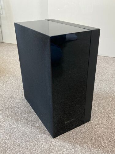
I have this existing Soundbar in living room ! Not a great one but not so bad either:
Its a 50 W stereo speaker with built in subwoofer , a Aux in, Optical & RCA In and of course a BT 5.0 !
So my next question is , if I am happy to use this Soundbar for now , can I skip the amplifier and bookshelf speakers ? Not that I don’t want to spend but just thinking if it’s possible to use the existing Soundbar I have !
Also I only have a Projector and not a TV , that sends the laser beam on to my projector screen . I have a fire TV stick connecting to HDMI 1 of projector and another Pi 4 with OSMC (Kodi) installed and connected to HDMI 2 of projector ! Both fire stick and Kodi connect to Soundbar using BT !
Table below the projector screen has
a. Another PI with Hifiberry Digi plus card (192 kHz / 24 bit , optical out ) with Max2Play installed and connected to the Soundbar through an optical cable ! The Pi basically acts a HIFi multi Room Music Streamer and Bluetooth Audio Receiver !
b. My Sound Bar and
c. Alexa Echo Show
Can I just install the new PI with usb sound card & mic (Rhasspy Satellite) and place in on the table beside echo and Soundbar ? Is that bad acoustics and placement for mic ?
Yep, just get the plugable USB as wired or local it can still be used and unlike a hat (2mic respeaker) you can use multiple and also just as a usb soundcard.
Just use the Aux In.
The Max9814 boards being wired just make it easier to mount and isolate than the 2mic due to being a hat it becomes all part of the pi.
Most people have the 2mic which is a linear board pointing at the ceiling because that is how it fits, but really the whole Pi should be vertical or use a 90’ connector.
Thats a 2mic hat 90’ it still becomes hard to isolate and Pi case don’t fit, so actually those Max9814 boards become a little easier as isolate those and the wires to the soundcard are flexible.
We are going to drop the pixel strip from the Mic, maybe still get one as they are cheap but need the logic level shifter.
Pi gpio is 3.3v whilst WS2812b is 5v and the above is supposedly bidirectional, so we can get it working and then worl out where ever it might go after, never tried so that bit for me is an experiment.
PS I have only ever seen these on ali-express but they make working with dupont jumpers when you need a common so much easier.
They are very cheap and handy for all sorts of gpio based connections and cuts down the solder jobs. https://www.aliexpress.com/item/1005003093298771.html
But basically as start its just to wire up x2 of those max9814 to a 3.5mm stereo jack to plug into the USB soundcard which is usually a screened pair Left/Right with screen being gnd, but also an extra 5v as the boards are preamps and powered.
Basically a DiY version of Array 2S Microphone - Andrea Communications which wil be better due the Max9814 and certainly not paying $45 for what is just a usb stereo ADC soundcard as the plugable one is every bit as good.
I haven’t drilled the holes and fitted the electrets in grommets but that is the test enclosure I am going to use and basically it will be just like the above andrea communication one but an active mic than passive that similary plugs into a stereo adc sound card aka Plugable.
Once again thank you for your guidance. You have been really incredible and your sound engineering expertise is immensely helping me understand the best practices for setting up Rhasspy ! Who have thought that an expert like you would be so willing to share his expertise and guide us ! That’s the real benefit of open source culture and I am absolutely loving it ! Thank you again !
I am trying to understand a few electronics basics with your help here. Apologies if they are sounding so basic but I am not experienced in hardware so much compared to my Software knowledge !
Why are we choosing electret mic instead of mems mic ? Is it because they have some kind of self noise cancellation from the back as compared to mems ?
How does the AGC on Max9814 help. Is it preamplifier ? Do we need it to increase the strength of microphone signal ?
How does Max9814 board with electret mic help towards overall noise cancellation alongside AEC or External noise cancellation ?
Why do we need to isolate Max9814 with electret mic ? Are we isolating it from noises and inferences coming from Pi ?
Does it mean can I use more than 2, say 4 Max9814 boards ? Does it help in far field voice detection or better direction or something else ?
If I use Max9814 boards , does it mean I don’t need a 90’ connector on Pi anymore as we are not using a HAT !
What’s the reason to prefer a usb sound card that has stereo mic input ? Does stereo mic input give us better voice capture features or something similar compared to mono ?
If I find a USB Sound card with stereo input 96 kHz sampling rate (something like a creative sound blaster) can I prefer to use it ?
I know I am sounding crazy on sampling rate numbers but if we use software AEC then anyway does it bring down the sample rate of music playing through the sound card Aux out to 16 kHz ? I saw that many hardware manufacturers such as those who make Remax 2 array USB with hardware dsp have only 16 kHZ. Does AEC limit the sampling rate to 16 kHz ?
I know that’s too many questions to ask ! I m only trying to learn some hardware basics from your experience ! If I set it up all correctly yes I will publish a DIY guide with due design credits to your knowledge !!!
Sound engineering expertise is purely referential as for some reason very little sound engineering is applied anywhere and my input is really rudimentary.
Electret is because of the Max9814 as its a sweet low noise preamp including selectable gain and AGC params.
There are mems avail but the preamp isn’t so sweet or has AGC.
Try them and see what you think as they are analogue and there is Speex AGC from the Alsa plugins.
I have selected the ones currently as the electret is onboard and its just less solder job and plug and play as my true preference is for these ones. Also being round they are extremely easy to mount in a grommet as with the mems avail those boards without even a mount hole are a pain.
As then you can choose the electret and swap from onboard omni-directional to one of the precursors to digital AEC of uni-directional noise cancelling electrets.
Or Farnel or RS unidirectional with the best sensitivity you can find.
They are front and rear ported where the rear port cancels as its in antiphase and that is my real preference but for some sourcing and soldering can be daunting so just went for ready made.
Its pointless to sample anything above 16Khz for the input to ASR as all use 16Khz or lower (near all use 16Khz) as 32Khz will double the load, 48Khz treble it, in fact it could be expotential and not linear and far more.
Also thinking this thread should be just trying some of your questions and getting some consensus so would be great if you had similar and that plugable is great value and good quality.
Could you please confirm if I am choosing the right hardware below to match our correct specifications / requirements ? I am a hardware noob at selecting matching specs, So trying to ensure I do not blast or burn anything !!! I will be ordering them today !
2x Max9814 with Electret and AGC
MiniBuck converter for pixel Led & Max9814 boards
Mini Buck converter for running Pi via GPIO 5v
Instead of this, can I use the one listed in point 2 above as it has a nice display ? However my concern is it has only 3A and a 5A is not available in pi hut !
Hard to find this brand elsewhere in UK and eBay just has so many duplicates ! Lucky I found one on Amazon UK !
2.1 Amplifier - I have decided to use an amplifier and bookshelf speakers for Rhasspy instead of use my existing Soundbar as it serves some other purpose !
I just need to look for
100watt 5/6amp 24v PSU
Bookshelf speakers
Ground Loop Noise Isolator
Audio Cables for Speakers
Arent Bookshelf speakers active and therefore connect to sound card / dac instead of Amp ?
Stereo 3.5mm jack lead with pigtail end to connect Max9814 to sound card
Just wondering how I can connect 2X Max9814 to USB sound card. I have seen your post from below but it talks about connecting to only one Max9814 !
Could you please let me know if any of these pi jumper cables are essentially useful for my Rhasspy DIY ?
Of course I can borrow a solder iron from a friend for very light soldering !
Yeah those look Ok and Pihut is a great shop and much of this are all Adafruit designs. If your happy with those prices then go for it.
I don’t usually like the adjustable bucks purely as its just more to think about and set, but I guess it does give you some tweaking room for the LED.
For a Pi GPIO power I would stick to 5v fixed as your jumpers should be short and at least no mistake can be made.
Again the boards I think are identical with the ‘I2C’ level shifter and dunno as have never tried but the freq should be able to cope with the 800khz Led control.
Plugable buy from amazon as have one on my desk that looks like one but definately isn’t purchased from ebay.
Use your echo or sound bar as a stock gap and you only need a Isolating transformer if using a buck from the Amp PSU to power both Pi and Amp.
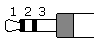
The 3.5mm TRS Tip/Ring/Sleeve I forget L/R Tip/Ring or the other way Ring/Tip but doesn’t matter the Sleeve is the Gnd and that is the screen.
I have just the 3.5mm solder jack and some 4core + screen cable and about the only thing I can not find breakouts or terminals for.
Pi jumpers female/female always come in handy often I snip them in half and solder to cables.
Short/long female/female but tend to never need female/male male/male ones.
PS maybe also (you prob have already) an el cheapo single usb soundcard as you can also split the max9814 and on multiple cards but different pick up areas as a comparison. Again a couple $ and no imminent need as is an el cheapo lapel/car mic if you do an ebay search.
With your 3.5mm fly lead terminate with spliced female dupoints so you can swap between the 2.
If I remember rightly its tip& sleeve as the ring is something called ‘bias’
This presents the pinout and explains well as there was never really a standard, just most copying soundblaster cards.
Thank you for confirming! I had ordered all the above and a few of them will arrive within next week . I went with two buck converters one with the display and other with fixed 5V as you have suggested ! Still need to order some cables and speakers though.
I was just wondering how we are doing the speaker enclosure or if you suggest to use separate enclosure each for speakers, Pi & mics for better isolation !
Does any of the below work as terminal block for 3.5 mm Jack ?
Also do I need these to avoid soldering ? I mean can’t the headers on pi gpio use DuPont cables ? Also correct me if I need connecting anything else on the Pi pin headers apart from below !
Buck connector for led pixels
Buck connector for powering Pi from GPIO pins
level shift connector
Connecting Max9814 to Pi GPIO voltage pins
Just looking if I can avoid soldering all together in the whole solution ?
Also I guess I was able to find screw terminal blocks for 3.5 mm Jack as I mentioned in previous post and am guessing I can avoid that soldering too ?
Not that I hate soldering but yes I prefer to avoid it if possible !
Sounds a great Idea ! Yes so I was thinking of :
Pluggable USb sound card hooked to 2 Max9814
Another old creative Sound Card I already have. Hook it up to 2 more Max 9814 or may be a lapel/car mic ! Or lapel mics any better without AGC and amplification of Max9814 ?
I can still route Audio only through the Sound card I want and enable AEC for that . But how can we do echo cancellation if voice is picked by mics attached to sound card 1 and audio was playing through sound card 2 ?
Its the stereo TRS not TRRS even though the 2nd ring of a TRRS that on mobiles and such is used for the mic it could be possible to use that as the 5v for the active mic we are creating.
If you have managed to borrow a soldering iron I wouldn’t bother as having no soldering is great but they are big unweildly lumps, so up to you but prob hack away with what you have got so you can make a decision later.
There is a big question with AEC & Beamforming on a Pi if the results are worth it, or creating a cheap simple mic(s) of close proximity as even a Pi02 can run more KWS than it has threads and just add another USB or split a stereo soundcard to x2 mics of different catchment areas.
So just get the Mic stuff plug in to any powered speaker you have and without doubt if you still have the enthusasm next steps will be Pixel strips and Active speaker systems.
About the only thing I am certain about is that those Max9814 active mics being a preamp with AGC are a good start as often the gain circuit in soundcards is lacking.
So before you spend on all the extras I am wondering after your experience if you think AEC / Beamforming is worth the effort and effective.
Each one impacts on another and sometimes effects can be subtle but accumalitive and then the comparison to a single simple mic in close proximity.
Much of the problems are due not due to latency as in length of time but the variable latency the scheduling on a application SoC will provide.
So after trying various combinations ist likely try it again with a custom kernel such as
Asking again the question is it worth it.
You being software orientated there are some repo’s such as alsa-plugins, voice-en-aec & even Rtprempt Kernel and more that likely should have community forks so community hacks and fixes can be applied.
The answer could well be that actually we might be trying obselete methods and targetted blind source seperation is the way to go, but more than that the latency with USB is a problem and the variable latency of an applications SoC means really the answer lies on a true RtOS all embedded hardware.
Even simpler things as testing does potting the enclosure of the mic help with rear rejection and resonance through surrounding materials and once more is it worthwhile bothering with…
Thanks for the details. While I am awaiting the parts, I am still scratching my head on how to connect two mac9814s to a single UB sound card ! While connecting a single Max9814 to a usb sound card is pretty clear ! Could you please detail on how this can be done ?
Sorry for being so noob ! I am still not clear ! Can you provide a clear detail of connections between Pi , 2 Max9814’s and stereo 3.5 mm Jack cable with terminal blocks ? That would really help !
I will just tell you how I have done it as the terminal ones are too bulky for me.
I have a 4 core + screen cable but not using a core. I have Tip = Left, Ring = Right, Sleeve = Gnd (screen) soldered on a standard 3.5mm TRS jack and a dupont going to 5v.
Other side Left goes to 1 Max9814 with common Gnd & 5V, right goes to the other with common Gnd & 5V.
Well my question is mostly on Pi side! I am trying to think how to hook two max 9814s to Pi . As I said I m pretty noob in hardware so an actual explanation on how each connector from max9814 goes to Pi and usb card ! Thanks .
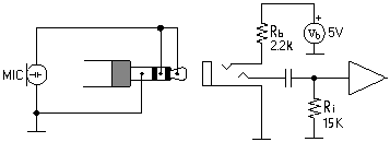
Note: A few, recently manufactured PCs have implemented true stereo microphone inputs. High performance speech recognition and advanced noise canceling applications – see the Andrea Superbeam Array stereo microphone – make good use of this new feature, providing more accurate and reliable signals in noisy environments.Stereo computer microphone schematic diagram
When the stereo mic input mode is selected, the bias voltage will be provided for both the tip and the ring. The wiring for a stereo microphone is simple – see the schematic diagram on the left – connect the shield of both microphones to the sleeve of the plug, the left mic to the tip and the right mic to the ring. For best performance, use unidirectional electret microphones.
One extra core needed for 5v from Pi5v to Max9814 5v not via jack plug. Haven’t soldered mine up yet but will post a pic.
Thank you. Sorry my mind has been somewhere throughout the day and just looked through this now and figured out as below :
Now that we have two of the below :
First or left Max9814
Second or right Max9814
The connections will be
Tip of 3.5 mm Jack = to Vdd pin on first Max9814
Ring of 3.5 mm Jack = to Vdd pin on second Max9814
Connect GND pins of first and second Max9814 and connect it to Sleeve (GND) of 3.5 mm Jack
Also connect Vdd pin on either of Max9814 to 5v on Pi (possibly Pin 2 or Pin 4)
Now that both Max9814s are in parallel , I need not worry as will both get the same voltage from Pi ! Also does it mean I cannot connect more than two Max9814s in parallel because we have tip and ring connecting to two Max9814s already !
And yes since we are about to use an amplifier PSU so we needed a Buck converter to step it down to 5V.
May be another rookie question - so are we leaving out Gain, Out and AR pins on both Max9814s ? This is the part I was getting more confused when I asked those questions to you in morning !
PSU is the only thing I haven’t bought , though I bought the Amplifier & other stuff as discussed ! So do you think a 100W, 24 V, 6A will cover our all needs of Pi, Led strip and Max9814s ? The 6 A is the thing I was getting concerned as Pi 4 requires 3.5 A and 1.8 A for Led strip ! That’s leaves another 0.7 A which is sufficient enough for both Max9814s ? I understand from data sheet that Max9814 draws very little current anyway …but please correct me if I am wrong ! (Afterall I am a rookie at electronics )
Yep that is what I am going to do, splice some female duponts as they are too fiddly to crimp.
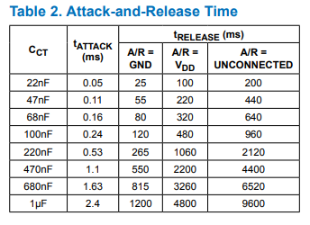
I have those 2x 5pin headers though as a splitter for 5v & Gnd, also the AGC A/R (Attack release) pin I am going to leave as float, so no connection needed.
The gain as from memory the top gain 60db is a bit noisy, 50db is connect gnd so on that splitter it works perfect gnd-in splits to each max9814 gnd & gain pin, and 5v-in will just split to each 5v supply.
I haven’t added a pic of the cable as still scratching my head to where I have put the heatshrink and 3.5mm jackplugs that I have had for some time.
The CT capacitor Adafruit choose and all are copying was mid table whilst really for voice the slower attack and release would be better as the noise would take longer to occur and only during low input and silence.
With AGC Attack and Release almost logically seem to be the wrong way round but Attack is a fast response to clipping to attenuate and Release is a delay before the gain will start climbing to Max Gain.
Saying this as the Alsa-plugin for Speex-AGC has a single parameter which is effectively like the capacitor and it lacks a Max-Gain which is an easy fix as similar happens as it just ramps up into a noise floor.
? Confused.com as said the out pin as you have x2 goes to the L/R of the 3.5mm which is the tip and ring?
On an el-cheapo I think the is the bias voltage and likely 5v buy dunno if it has the rated current for a preamp as is only designed for the tiny electret current, but maybe could. I just keep to a seperate 5v.
Huh so difficult to figure it out as a noob especially when its in bits and pieces and I had to stick it together !
So as we discussed the full set of connections are
The connections will be
Tip of 3.5 mm Jack = to Vdd pin on first Max9814
Ring of 3.5 mm Jack = to Vdd pin on second Max9814
Connect GND pins of first and second Max9814 and connect it to Sleeve (GND) of 3.5 mm Jack
Also connect Vdd pin on either of Max9814 to 5v on Pi (possibly Pin 2 or Pin 4)
And finally,
out pin as we have x2 goes to the L/R of the 3.5mm which is the tip and ring !
Are these the full set of connections between Max9814 and Soundcard !please let me know if I am missing anything ! I guess all the pins on Max9814 are covered now .
Nope tip first max9814 out.
Ring to 2nd Max9814 out.
Sleeve common Gnd to both.
5v from GPIO to 5v on both.
Link Gain to Gnd.
That is with a plugable stereo ADC soundcard.
On a el-cheapo (single) mic the ring is the 5v (probably), tip is out and sleeve is gnd. Which I think makes the best budget conscious mic with some minimal solder of duponts to a 3.5mm flylead like you have got.
Most sound card microphone inputs require a minimum signal level of at least 10 millivolts, but some older 8-bit cards need as much as 100 millivolts. The typical impedance of the PC soundcard microphone input is in order of 1 to 20 kohms (can vary from card to card). The microphone type which works best with computer sound cards is the electret microphone.
Sound Blaster soundcards (SB16, SB32, AWE32, AWE64 or Live) from Creative Labs have a 3.5mm (1/8 inch) pink stereo jack for the microphone input, with the following pinout:
Signal input (tip)
+5V bias (ring)
Ground (sleeve)
Note: Most soundcards will wire the positive DC bias voltage to the ring, but a small number of non-standard soundcards can have the bias voltage wired to the tip. A few cards have a jumper which enables or disables the power to the microphone jack. If the jumper is put on, the bias voltage ( +5V through a few kiloohm resistor) is wired to the tip. Newer mainboards with stereo microphone support will provide the bias voltage for both the tip and ring.
The approximate schematic of a Sound Blaster microphone input circuitry shows that the +5V voltage on the connector is heavily current limited. The card’s voltage might not be exactly 5V, but it is usually something between 3 and 5 volts when no microphone is connected.
So likely they maybe 5v but not enough for the preamp and the preamp just boosts what are often relatively quiet desktop mics to give that touch more far field than the design of use which is a close proximity ‘broadcast’ mic.
I am going to pot my enclosure in resin and build up anaother with uni-directional, what I have done so far is got you some basic elements to play around with to make a possible stereo beamformer or split into 2 mics of different coverage or just use a single mic.
As going back to the ‘is it worth it’ when you have raised the gain of an el-cheapo is all the extra worthwhile…
Same with enclosures ‘is it worth it’ as at 1st don’t bother try out various configs and then make an enclosure later and compare.
All I am going to do is fill my mic enclosure in resin, so its solid, dense and less prone to resonance but its sort of permanent. So don’t as you might decided you just going to split and run 2x mics or whatever, so try some results 1st.
The Plugable is a newer stereo ADC design as in
Note: A few, recently manufactured PCs have implemented true stereo microphone inputs. High performance speech recognition and advanced noise canceling applications – see the Andrea Superbeam Array stereo microphone – make good use of this new feature, providing more accurate and reliable signals in noisy environments
.
When the stereo mic input mode is selected, the bias voltage will be provided for both the tip and the ring. The wiring for a stereo microphone is simple – see the schematic diagram on the left – connect the shield of both microphones to the sleeve of the plug, the left mic to the tip and the right mic to the ring. For best performance, use unidirectional electret microphones.
So its same circuit but connected to a preamp than just an electret.
I asked the above and when you only talked about Gain & AR pins I assumed the rest of it is correct ! But when I asked explicitly about out , based on your answers I was confused as I thought tip or ring are going to Vdd on Max9814 !
That means we are going to use one 5V pin on Pi right to connect vdd pin on each preamp ? Just wondering because we need the other 5V pin on Pi to power up the Pi !
Nope just add 2x duponts to the end of a single 5v that are long enough to go to each max9814.
sanyasa_sure where are you based as you seemed to get everything from PiHut which is a great shop (I am just a cheap skate and ebay and ali it)
Really that flylead makes things more akward needing an extra core for 5v that it doesn’t have.
I am using this 4 core as individually screened so 5v is in and also the LED control core.
2 cores + Gnd I solder to a TRS 3.5mm for 1st/2nd out and gnd the other 2 cores solder a dupont one to 5v and the other eventually GPIO through a level shifter.
Also it lets you create a much longer lead so we can do the comparison of farfield vs I will just place a small mic nearer.
4/6m of that cable will let you do both and a couple of stereo jacks that you solder…
I quite like the idea of using a 4 core cable ! I have also bought some of these 4 core cables from the link you sent as they seem to very cheap on eBay !
I have chosen the below 3.5 mm stereo Jack plug on eBay ! Let me know if it’s the correct one
In the 4 core cable you have mentioned below , which colors should go to tip , ring and gnd of 3.5 mm Jack plug ? Also what about the remaining two cores , should I leave them hanging as I cannot connect them to 3.5 mm Jack ! This is the part I am having doubts on !
So are you saying that for a 4 core cable as seen above , 2 cores (for example white and black )+ copper can be used for 3.5 mm Jack ! And on the other side remaining 2 cores (for example red and yellow ) can be soldered with DuPont so can be used to connect to GPIO 5 V and also for level shifter ?
Also I am thinking, I will solder jumper wire & DuPonts to each of the 4 core cable on the other side. I will then solder a 5 pin header for each Max9814 preamp which is super easy so I can then connect using DuPonts then ! Is this the correct approach
For common gnd , I was thinking I will use copper color to connect to gnd of Jack plug on one side. On the other side I will connect 2 DuPonts so that each goes to gnd port of Max9814s ! Is this the correct approach !
Even for the core that is not connected to 3.5 mm Jack plug I will solder 2 DuPonts so that each goes to Vdd of Max9814s ! But how about 5v GPIO of Pi ? So should I solder 3 DuPonts instead ?
I have just bought a soldering kit from eBay for cheap ! I don’t mind some soldering which seems to be the best bet for our DIY anyway !
While I am awaiting the arrival of other items, I will try to solder the wires (4 core soldered to 3.5mm Jack plug on one end and DuPont jumper wires soldered to other end )and post some pics !
Also I could find a 100 W 24 V PSU on eBay . The one on aliexpress has only a eu plug which doesn’t help much . Could you post a link for the correct one on eBay if you can find one please ?
Often Red & White is used for L/R so do but colours are purely up to you.
2 cores to the 3.5mm ring & tip, screen to gnd. The other 2 is 5v so a dupont and the remaining that if not using the 5v LED control for the pixel strip just don’t use or double up so the 5v has more copper.
I think I am showing my age but I prefer 3.5mm jacks with the bigger solder tabs that are more old school, but yeah they will be OK.
Yeah splice some female duponts as really you could just hard solder but whilst just playing with best settings the duponts make it easier than changing anything hard soldered.
Depends on your choice of amp as likely in running the supposed ‘2x 50watt’ will be more like 2x30watt max and this will do.
Or a 5amp one here
Just the 1st ones I found but you can find better deals with UK plugs on ebay and ali if you do some searching.
I wouldn’t bother yet as starting with the mics I am just going to use my Alexa as an active speaker for now.
Do you think 3 A is enough current for Pi, LED Strips, Amplifier and Max9814s ? I actually like the second one that gives a option to choose 24V 5A . But is that tto much ?
Yeah get 24v 5a as not expecting it to get anywhere near rated, can not check as actually what chips is anyones guess, my initial guess it will prob be about 30watt is prob about right L+R = 60watt and give 60 for sub then 120watt so 24v5amp and to get that bet its likely you need 4 ohm speakers.
Thanks, Also just curious along what speakers you would use or recommend ! Should it be a proper bookshelf speaker or a chassis speaker as we would like to build our own enclosure in the long future after through testing & tinkering ! It would be great if you could post some picture of speakers that you have or something in eBay that you would like to buy ! Just gives me a clear idea as my intention was to build up a custom enclosure somewhere down the lane !
Totally up to you, but no point going crazy as the amp you got will give a great sound, but its no studio amp.
P&P is often due to bulk is what tops up the cost but anything in the $10-20$ with prob $5 P+P
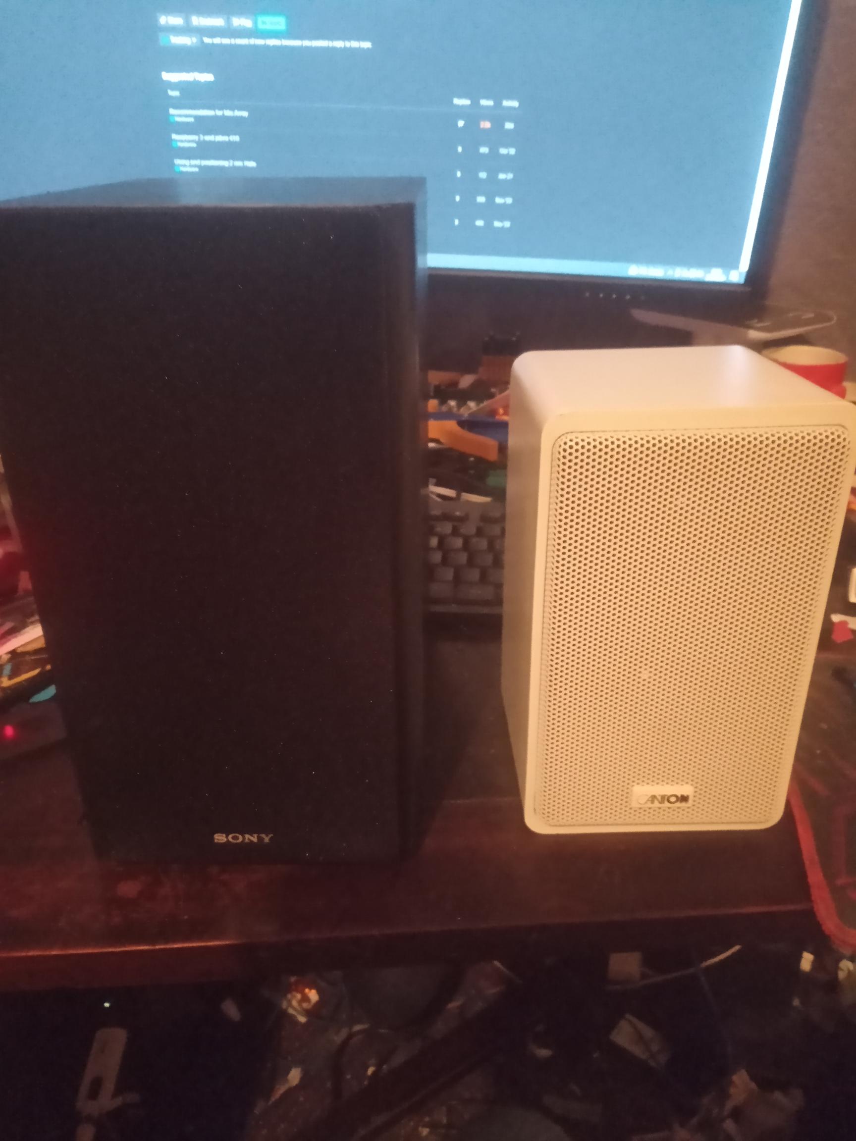
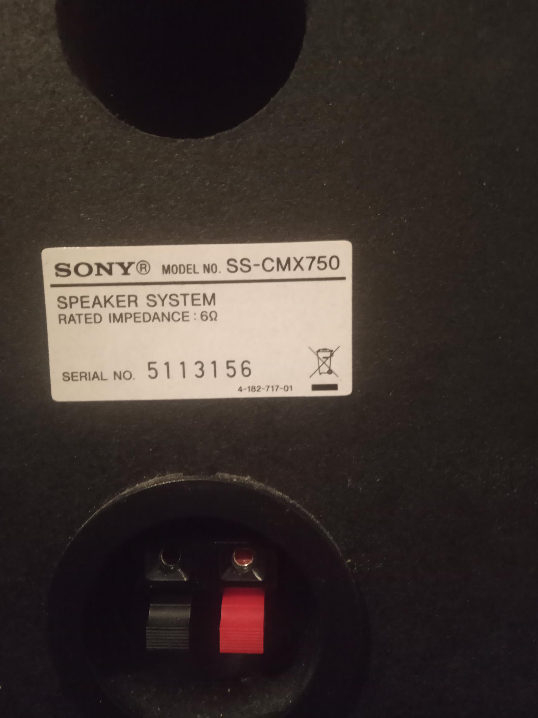
The Sony is just a pair from what would be a budget midi hifi unit and a pair cost me £12.99+£5.99 if I remember correctly.
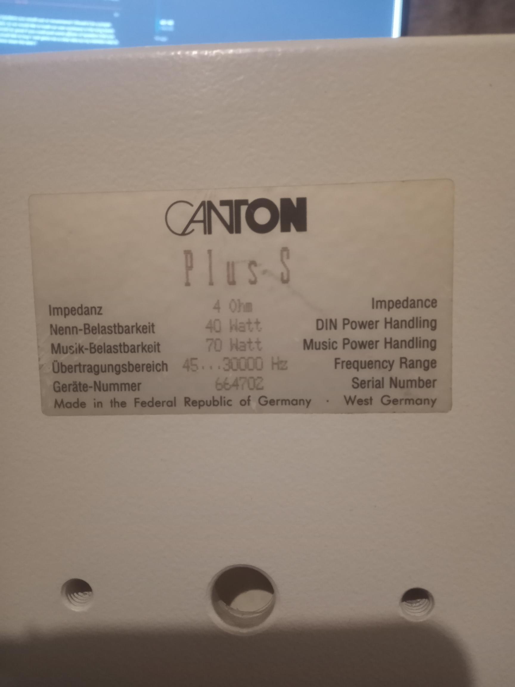
The Cantons where £20+£6.50 which are older but a good German make.
Likely the Canton’s of a higher quality than the amp and something like the Sony’s would be perfect.
Subwoofer likely you will have to get seperate but if you are in no rush often ex passive home cinema ones will turn up for £10 or less and again P+P can be a pain.
Take your time, throw a max bid on of approx about that, fail a few times. Ebay can be strange at times but if your patient you can often find a lull and low price.
Also I have the following hardware - and intend to use one of them for Rhasspy base !
I have an Intel NUC - celeron quad core with 8 GB
Mac mini 2011 with i5 core 2 duo and 16 GB (hyper threading enabled so basically it acts as four processor cores)
I was using Home Assistant inside virtual box VM on Mac mini ! I just moved the Home Assistant to Intel NUC over the weekend ! So now I plan to repurpose Mac mini as a Ubuntu Server so I can use Rhasspy Base and MQQT !
I managed to get a Pi 4 GB from a friend ( helped him with his home assistant / zigbee / Zwave setup and he gave his extra Pi 4 GB for our DIY)
So when we start testing and tweaking noise cancellation or AEC algorithms - they generally run on Satellite right ? If that’s the case then our satellite on 4 GB Pi has enough juice right ?
I thought we where using Pi02 and you had one? As the Pi02 for what is not much more than a wireless microphone its cost seems far more relevent especially with gear, psu, case, sd card, usb, mics or hat…
Both what you have are pretty stinky as lack AVX and likely less than say an Opi5 or another RK3588 likely is far more ML capable.
I did for a while consider GPU based 2nd user PC’s but with what has happened with energy and where its likely to lead, they are have really lost any refurb shine.
Its a huge problem at the moment as Pi02 expecting a price hike when avail in 2024 likely close to Pi3A+ which is a great SoC.
Satelite is such a weird term and would seem a strange clone of commercial hardware models that really for me in terms of a KWS activated broadcast Mic Array, eventually it will be microcontrollers and likely could be an ESP32-S3.
I am always exploring and my latest purchase was a Pixel6a phone as it has the same Tensor NPU as its bigger brothers and the CPU & GPU also ramp up into another league even if the previous series as a 20 core.
CPU: 2x 2.8 GHz ARM Cortex-X1, 2x 2.25 GHz ARM Cortex-A76, 4x 1.8 GHz ARM Cortex-A55 ; GPU: ARM Mali-G78 MP20
Its interesting as Android13 that I have still to test has pKVM (KVM virtualisation) but also native NNapi drivers make things much easier for interoperability and I picked up a refurb for £200.
Its crazy at the moment as Arm phone chips and crazy powerful Apple silicon AKA M1/M2 when it comes to ML don’t just have Mhz, low wattage, but specific instruction sets with ML instructions and wide bus vector co-processors that have been designed for DSP/ML…
Ok I get it ! Yes esp-32-s3 seems to be very exciting and works well for a satellite with hardware supporting algs for noise cancellation, beam forming or echo cancellation and so on ! It also is an RTOS like you mentioned prior so ticks several boxes ! I plan to setup a second satellite using eps-32-s3 dev kit in the future !
But don’t we agree those esp based satellite are only good at voice recognition capabilities but not audio playback capabilities! I haven’t seen many that give atleast 48khz sampling rate ! They mainly lack in DACs ! So for that set of folks looking to combine a Rhasspy Satellite with HiRes music playback capabilities it’s still not so viable solution !
I have a Pi02 lying around too , I almost have 4-5 Pi based projects ( music streamers, Video doorbells and aquarium camera ) and so have a Pi02 and Pi4 lying empty at the moment waiting to be used !
Any esp32 doesn’t have any limits as it doesn’t have a built in DAC and its dependent on the DAC you attach to its I2S port.
RaspiAudio and there SqueezeLite ESP32 prob would take exception to your claims, but really its the Pi that has shortcomings as it only has a single free I2S port and much of the protocols are bitbanged software as opposed to the 2x fully compatible hardware pheripherials on the esp32-S3.
The Pi has Dacs that means no input audio as they take up the only available I2S port and you have that totally the wrong way round as on the Pi you are limited various specific Mic hats or usb sound cards and with the hats you are limited to one, so for a satelite it becomes a single input and even on a Pi02 that likely means much sat idle.
PS satelite means little to me as that all is needed is a KWS activated wireless mic array and maybe the akward fit of a Pi for this purpose is the reason to bloat that need to whatever a satelite is.
The analogy is that the EspHome/Tasmoto devices are not going to be specific and we call them a satelite and use a Pi for instead and find some other things they can do.
We don’t as all is needed is a platform that is cost effective and fulfills a specific need as microcontrollers do and exist for this purpose.
To be honest I have no idea what a voice assistant satelite really is as a voice system is that and its and audio in and out system, its only commercial Big Data who employ that peer2peer to sell more consumer equipment…
Its very much the other way round with the Pi and a Rhasspy satelite that misses the essential input audio processing and I going to try and do as much as possible with the AEC and Beamforming that is available and will let you play with the ‘satelite’ side but for me the concept and need is alien and a bad fit from cost to function on Pi, its just advantageous due to easier higher level languages that run on a application OS and accomdates users more than function.
I am also looking at audio loop back interfaces that are useful for implementing AEC algorithms. I know we haven’t got there yet but just curious while awaiting the shipping of components !
So when we are using the stereo USB sound card for our DIY, are we planning a hardware audio loop back or software audio loop back using Alsa for testing AEC algs ?
Also what connections need to be made to create a Hardware Audio loop back assuming we have a sound card with enough audio in and out interfaces ? I am very curious to understand the cabling and connections to create a hardware audio loop back
Also just very curious if we can connect Max 9814s to existing hats like IQAUDIO codec board or something like below:
No I don’t want to use any of the above and happy with using our stereo USB sound card ! But trying to understand if it is really possible to use any of the above listed sound cards and connect them to two Max9814s as they seem to have stereo Line Inputs !
Hardware loopback is essentially just a spare ADC channel that the output DAC feeds and it creates an audio sync.
With cards with a audio in/out sample on sample the shared clock gives no clock drift, which with seperate audio in/out via 2 clocks each sample might be prone to drift on each sample and AEC just never syncs.
Without a hardware loopback there is no direct inject and sync and there is a latency of capture and process that is prone to change due to the nature of scheduling on a non real time OS but AEC is fed audio in chunks so its effect is degraded as it tries to sync but when it does the samples of that chunk all remain the same. So with a shared clock you can but the variable latency delay of a single clock audio in/out is still problematic as AEC wil sync but chunk by chunk it will initially drift.
That is something this time I really intend to exhaust all avenues looking at latency chunk size & RtPrempt Kernels and why we have the cheapest $15 stereo ADC soundcard that allows user configuration and placement of the 2x mics.
Likely though Blind Source Seperation that doesn’t need a synced ref signal (Blind) where a mic array is not sat ontop of its speaker or any speaker will work much better for all (3rd party), we just lack the realtime algs on a Pi.
Ok so on our DIY when we use the Pluggable USB Soundcard , Both the ADC channels are used up by both Mics (Max9814s) right ! That means we don’t have a spare ADC Channel to do a hardware loopback ? Am I right in understanding this ?
Yeah as focus is to try with a $15 soundcard that you can have multiples of is to try and reduce latency and scheduling effect to a minimum as to be honest we are not going to invest much $ into AEC as its only for what its playing locally, which is limiting.
Ok does it mean we are implementing AEC with Alsa software loopback and not bang into $ to get multiple ADC Channels just to get a hardware loopback ? I understand that but I guess we need a minimum aec implementation at the least !
Will have to see at what price its an A35 which cunningly Arm named as its a low energy A53 pi3 like Soc.
No GPU but has onboard 8 channel ADC same SoC as the Radxa RockPi-S that I did get and was a fail for me at least due to noise on the ADC.
Yet another SBC that I will prob evaluate when avail.
The board sounds wow!!! with 8 ADC and 2 DAC … which is really a dream to combine a voice assistant and Music Streamer ! Just wondering if we can we use Max 9814s with the board ?
If its like the RockPi-S you just need differential wired electrets as bias and AGC is part of the codec.
My memory sucks bigstyle as did try on the RockPi-S but was far too noisy, but maybe they have got that sorted and Top Banana, it is.
Before I forget part of the reason why usb of either 1/2 channel and you can 2 or more instances on either the ‘base’ or ‘satelite’ with many of the SoCs.
That is the 4th core ‘Pixel strip’ for a wired remote additional mic(s) with or without a ‘on-device’ one.
Also an endfire is a fixed distance static delay&subtract (one behind the other) and makes the mic more directional (cardioid), limited by channels and unidirectional mics being a bonus. The alg adds hardly any load as the broadside is 95% TDOA to beamform to get the delay.
Soundcards generally are geared up for a broadcast style distance (close talk) and lack the gain, even in near field, where the Max9814 is just a low noise preamp I like, adding a preamp extends into nearfield.
That can be expotentially better than digital gain of a low signal and filters from GitHub - SaneBow/PiDTLN: Apply machine learning model DTLN for noise suppression and acoustic echo cancellation on Raspberry Pi to simple hiss removal can be used also and artefacts are not a problem for a KWS if the dataset is mixed with noise and filtered and you train it in.
Also BSS that has no clue but seperates into x2 distinct streams where you select by running 2x KWS. JorisCos/ConvTasNet_Libri2Mix_sepclean_16k · Hugging Face
Likely heavy but quantising whilst converting to Onnx could be possible, or just simple multiple mics.
 As its not the distance of the noise its the ratio SNR (Sound to Noise Ratio) that KWS really start to struggle above 30% noise.
 definitely I would be very very interested in such a setup ! Absolutely let’s please do it ! I am an experienced Linux user as I am into software engineering for more than 2 decades now ! But yes still a noob when it comes to hardware but I hope if you guide me I would be able to try out the interesting setup !!!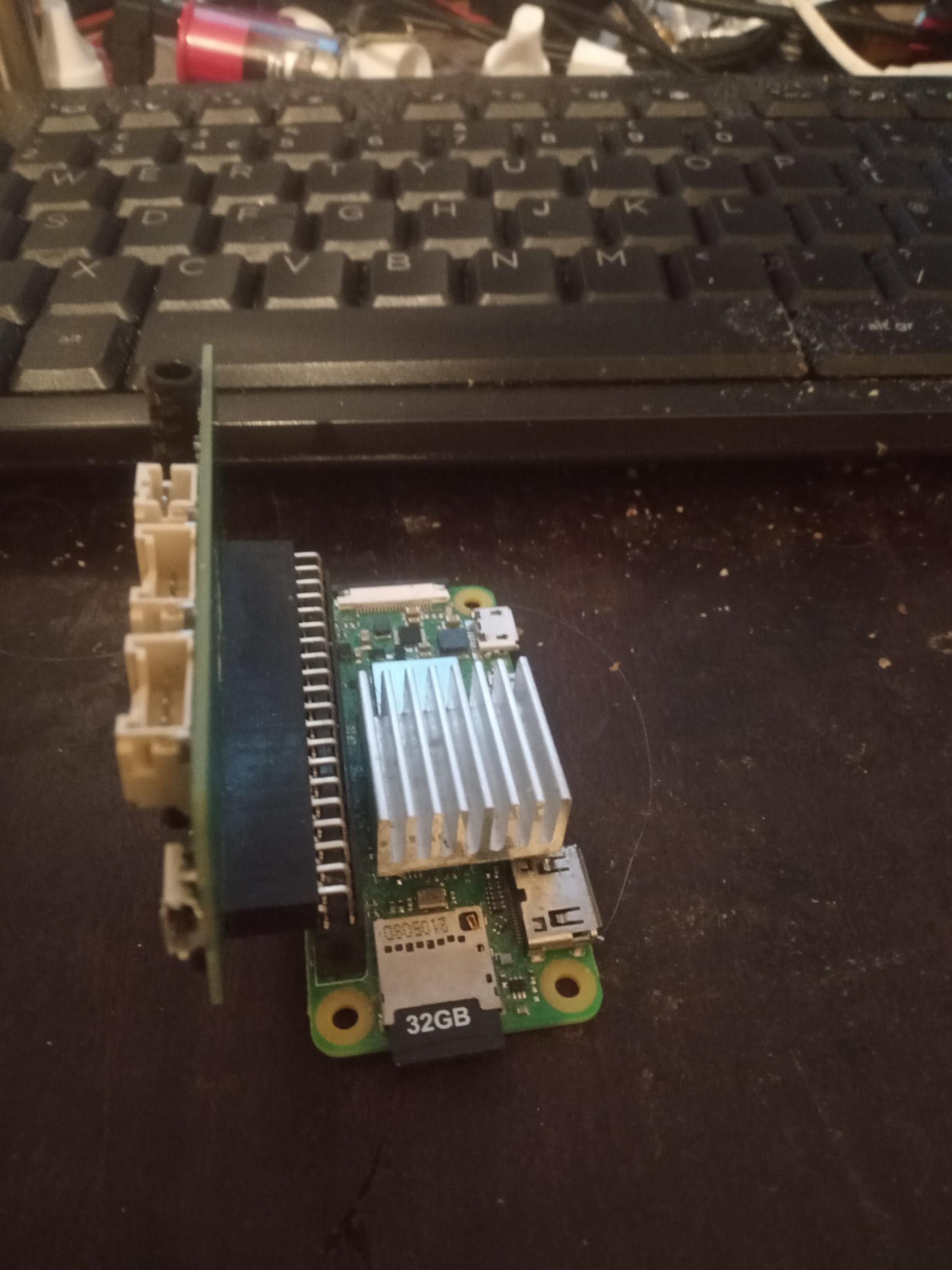
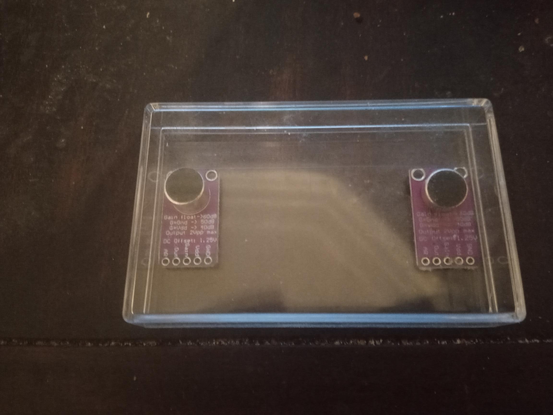
 for better isolation !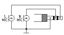
 I was only asking about the OUT pin!