Well my question is mostly on Pi side! I am trying to think how to hook two max 9814s to Pi . As I said I m pretty noob in hardware so an actual explanation on how each connector from max9814 goes to Pi and usb card ! Thanks .
Max9814 go to USB Plugable.
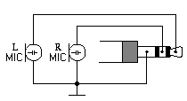
Note: A few, recently manufactured PCs have implemented true stereo microphone inputs. High performance speech recognition and advanced noise canceling applications – see the Andrea Superbeam Array stereo microphone – make good use of this new feature, providing more accurate and reliable signals in noisy environments.Stereo computer microphone schematic diagram
When the stereo mic input mode is selected, the bias voltage will be provided for both the tip and the ring. The wiring for a stereo microphone is simple – see the schematic diagram on the left – connect the shield of both microphones to the sleeve of the plug, the left mic to the tip and the right mic to the ring. For best performance, use unidirectional electret microphones.
One extra core needed for 5v from Pi5v to Max9814 5v not via jack plug. Haven’t soldered mine up yet but will post a pic.
Hello @rolyan_trauts
Thank you. Sorry my mind has been somewhere throughout the day and just looked through this now and figured out as below :
Now that we have two of the below :
First or left Max9814
Second or right Max9814
The connections will be
Tip of 3.5 mm Jack = to Vdd pin on first Max9814
Ring of 3.5 mm Jack = to Vdd pin on second Max9814
Connect GND pins of first and second Max9814 and connect it to Sleeve (GND) of 3.5 mm Jack
Also connect Vdd pin on either of Max9814 to 5v on Pi (possibly Pin 2 or Pin 4)
Now that both Max9814s are in parallel , I need not worry as will both get the same voltage from Pi ! Also does it mean I cannot connect more than two Max9814s in parallel because we have tip and ring connecting to two Max9814s already !
And yes since we are about to use an amplifier PSU so we needed a Buck converter to step it down to 5V.
-
May be another rookie question - so are we leaving out Gain, Out and AR pins on both Max9814s ? This is the part I was getting more confused when I asked those questions to you in morning !
-
PSU is the only thing I haven’t bought , though I bought the Amplifier & other stuff as discussed ! So do you think a 100W, 24 V, 6A will cover our all needs of Pi, Led strip and Max9814s ? The 6 A is the thing I was getting concerned as Pi 4 requires 3.5 A and 1.8 A for Led strip ! That’s leaves another 0.7 A which is sufficient enough for both Max9814s ? I understand from data sheet that Max9814 draws very little current anyway …but please correct me if I am wrong ! (Afterall I am a rookie at electronics
 )
)
Also if I terminate the 3.5 mm fly leads with DuPonts I can then connect them to Max9814 pins or soldering is better here ?
Yep that is what I am going to do, splice some female duponts as they are too fiddly to crimp.
I have those 2x 5pin headers though as a splitter for 5v & Gnd, also the AGC A/R (Attack release) pin I am going to leave as float, so no connection needed.
The gain as from memory the top gain 60db is a bit noisy, 50db is connect gnd so on that splitter it works perfect gnd-in splits to each max9814 gnd & gain pin, and 5v-in will just split to each 5v supply.
I haven’t added a pic of the cable as still scratching my head to where I have put the heatshrink and 3.5mm jackplugs that I have had for some time.
So its x4 gnds but you could prob just solder a link and make it perm than a jumper as from memory 60db is a bit noisy.
Really if you check the datasheet https://www.analog.com/media/en/technical-documentation/data-sheets/max9814.pdf
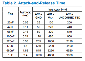
The CT capacitor Adafruit choose and all are copying was mid table whilst really for voice the slower attack and release would be better as the noise would take longer to occur and only during low input and silence.
With AGC Attack and Release almost logically seem to be the wrong way round but Attack is a fast response to clipping to attenuate and Release is a delay before the gain will start climbing to Max Gain.
Saying this as the Alsa-plugin for Speex-AGC has a single parameter which is effectively like the capacitor and it lacks a Max-Gain which is an easy fix as similar happens as it just ramps up into a noise floor.
Ok it makes sense now ! AR pin will stay unconnected ! But gain pin needs to be grounded !
So, I need to
connect GND & Gain pins of first and second Max9814 together and connect them to Sleeve (GND) of 3.5 mm Jack !
Thanks ! That helps to understand about those two gain & AR pins
Also what about the OUT pin on each Max9814 ?
L/R of the tip/ring of the 3.5mm jack and gnd to sleeve
Sorry ![]() I was only asking about the OUT pin!
I was only asking about the OUT pin!
? Confused.com as said the out pin as you have x2 goes to the L/R of the 3.5mm which is the tip and ring?
On an el-cheapo I think the is the bias voltage and likely 5v buy dunno if it has the rated current for a preamp as is only designed for the tiny electret current, but maybe could. I just keep to a seperate 5v.
Huh so difficult to figure it out as a noob especially when its in bits and pieces and I had to stick it together !
So as we discussed the full set of connections are
The connections will be
Tip of 3.5 mm Jack = to Vdd pin on first Max9814
Ring of 3.5 mm Jack = to Vdd pin on second Max9814
Connect GND pins of first and second Max9814 and connect it to Sleeve (GND) of 3.5 mm Jack
Also connect Vdd pin on either of Max9814 to 5v on Pi (possibly Pin 2 or Pin 4)
And finally,
out pin as we have x2 goes to the L/R of the 3.5mm which is the tip and ring !
Are these the full set of connections between Max9814 and Soundcard !please let me know if I am missing anything ! I guess all the pins on Max9814 are covered now .
Nope tip first max9814 out.
Ring to 2nd Max9814 out.
Sleeve common Gnd to both.
5v from GPIO to 5v on both.
Link Gain to Gnd.
That is with a plugable stereo ADC soundcard.
On a el-cheapo (single) mic the ring is the 5v (probably), tip is out and sleeve is gnd. Which I think makes the best budget conscious mic with some minimal solder of duponts to a 3.5mm flylead like you have got.
If you go back to Sound card microphone
Most sound card microphone inputs require a minimum signal level of at least 10 millivolts, but some older 8-bit cards need as much as 100 millivolts. The typical impedance of the PC soundcard microphone input is in order of 1 to 20 kohms (can vary from card to card). The microphone type which works best with computer sound cards is the electret microphone.
Sound Blaster soundcards (SB16, SB32, AWE32, AWE64 or Live) from Creative Labs have a 3.5mm (1/8 inch) pink stereo jack for the microphone input, with the following pinout:
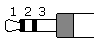
- Signal input (tip)
- +5V bias (ring)
- Ground (sleeve)
Note: Most soundcards will wire the positive DC bias voltage to the ring, but a small number of non-standard soundcards can have the bias voltage wired to the tip. A few cards have a jumper which enables or disables the power to the microphone jack. If the jumper is put on, the bias voltage ( +5V through a few kiloohm resistor) is wired to the tip. Newer mainboards with stereo microphone support will provide the bias voltage for both the tip and ring.
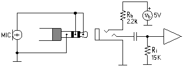
The approximate schematic of a Sound Blaster microphone input circuitry shows that the +5V voltage on the connector is heavily current limited. The card’s voltage might not be exactly 5V, but it is usually something between 3 and 5 volts when no microphone is connected.
So likely they maybe 5v but not enough for the preamp and the preamp just boosts what are often relatively quiet desktop mics to give that touch more far field than the design of use which is a close proximity ‘broadcast’ mic.
I am going to pot my enclosure in resin and build up anaother with uni-directional, what I have done so far is got you some basic elements to play around with to make a possible stereo beamformer or split into 2 mics of different coverage or just use a single mic.
As going back to the ‘is it worth it’ when you have raised the gain of an el-cheapo is all the extra worthwhile…
Same with enclosures ‘is it worth it’ as at 1st don’t bother try out various configs and then make an enclosure later and compare.
All I am going to do is fill my mic enclosure in resin, so its solid, dense and less prone to resonance but its sort of permanent. So don’t as you might decided you just going to split and run 2x mics or whatever, so try some results 1st.
The Plugable is a newer stereo ADC design as in
Note: A few, recently manufactured PCs have implemented true stereo microphone inputs. High performance speech recognition and advanced noise canceling applications – see the Andrea Superbeam Array stereo microphone – make good use of this new feature, providing more accurate and reliable signals in noisy environments
.
When the stereo mic input mode is selected, the bias voltage will be provided for both the tip and the ring. The wiring for a stereo microphone is simple – see the schematic diagram on the left – connect the shield of both microphones to the sleeve of the plug, the left mic to the tip and the right mic to the ring. For best performance, use unidirectional electret microphones.
So its same circuit but connected to a preamp than just an electret.
1 Like
Thank you it’s clear now !
Yes I confused for a reason !
I asked the above and when you only talked about Gain & AR pins I assumed the rest of it is correct ! But when I asked explicitly about out , based on your answers I was confused as I thought tip or ring are going to Vdd on Max9814 !
Thanks you . It’s much clear now
That means we are going to use one 5V pin on Pi right to connect vdd pin on each preamp ? Just wondering because we need the other 5V pin on Pi to power up the Pi !
Nope just add 2x duponts to the end of a single 5v that are long enough to go to each max9814.
sanyasa_sure where are you based as you seemed to get everything from PiHut which is a great shop (I am just a cheap skate and ebay and ali it)
Really that flylead makes things more akward needing an extra core for 5v that it doesn’t have.
I am using this 4 core as individually screened so 5v is in and also the LED control core.
2 cores + Gnd I solder to a TRS 3.5mm for 1st/2nd out and gnd the other 2 cores solder a dupont one to 5v and the other eventually GPIO through a level shifter.
Also it lets you create a much longer lead so we can do the comparison of farfield vs I will just place a small mic nearer.
4/6m of that cable will let you do both and a couple of stereo jacks that you solder…
1 Like
Hi @rolyan_trauts ,
I quite like the idea of using a 4 core cable ! I have also bought some of these 4 core cables from the link you sent as they seem to very cheap on eBay !
- I have chosen the below 3.5 mm stereo Jack plug on eBay ! Let me know if it’s the correct one
1x Gold 3.5mm Male Stereo Jack Plug 3 Pole Solder Headphone Repair & Upgrade UK
- In the 4 core cable you have mentioned below , which colors should go to tip , ring and gnd of 3.5 mm Jack plug ? Also what about the remaining two cores , should I leave them hanging as I cannot connect them to 3.5 mm Jack ! This is the part I am having doubts on !
4 Core Individually Screened Cable (2 meters) 5015972050361
-
So are you saying that for a 4 core cable as seen above , 2 cores (for example white and black )+ copper can be used for 3.5 mm Jack ! And on the other side remaining 2 cores (for example red and yellow ) can be soldered with DuPont so can be used to connect to GPIO 5 V and also for level shifter ?
-
Also I am thinking, I will solder jumper wire & DuPonts to each of the 4 core cable on the other side. I will then solder a 5 pin header for each Max9814 preamp which is super easy so I can then connect using DuPonts then ! Is this the correct approach
-
For common gnd , I was thinking I will use copper color to connect to gnd of Jack plug on one side. On the other side I will connect 2 DuPonts so that each goes to gnd port of Max9814s ! Is this the correct approach !
-
Even for the core that is not connected to 3.5 mm Jack plug I will solder 2 DuPonts so that each goes to Vdd of Max9814s ! But how about 5v GPIO of Pi ? So should I solder 3 DuPonts instead ?
I have just bought a soldering kit from eBay for cheap ! I don’t mind some soldering which seems to be the best bet for our DIY anyway !
While I am awaiting the arrival of other items, I will try to solder the wires (4 core soldered to 3.5mm Jack plug on one end and DuPont jumper wires soldered to other end )and post some pics !
Also I could find a 100 W 24 V PSU on eBay . The one on aliexpress has only a eu plug which doesn’t help much . Could you post a link for the correct one on eBay if you can find one please ?
Often Red & White is used for L/R so do but colours are purely up to you.
2 cores to the 3.5mm ring & tip, screen to gnd. The other 2 is 5v so a dupont and the remaining that if not using the 5v LED control for the pixel strip just don’t use or double up so the 5v has more copper.
I think I am showing my age but I prefer 3.5mm jacks with the bigger solder tabs that are more old school, but yeah they will be OK.
Yeah splice some female duponts as really you could just hard solder but whilst just playing with best settings the duponts make it easier than changing anything hard soldered.
Depends on your choice of amp as likely in running the supposed ‘2x 50watt’ will be more like 2x30watt max and this will do.
Or a 5amp one here
Just the 1st ones I found but you can find better deals with UK plugs on ebay and ali if you do some searching.
I wouldn’t bother yet as starting with the mics I am just going to use my Alexa as an active speaker for now.
1 Like
Thanks …
Do you think 3 A is enough current for Pi, LED Strips, Amplifier and Max9814s ? I actually like the second one that gives a option to choose 24V 5A . But is that tto much ?
Depends on your amp but 3amp is 72watt, but as usually derate a bit. 5amp is 120watt.
The Pi & stuff is so minimal just match the amp.
Ok I ordered the below AMP:
It clearly says - Adapter power supply: above DC12-24V/5A
so the word ‘ABOVE’ GOT ME THINKING IF 24 V & 5A PSU is adequate